by Steve Bygren, steve2822@earthlink.net
In the January, 1996 issue of Sky & Telescope, my picture showed up with a “servo focuser” gizmo that a member of my astronomy club (Ken Florentino) created. Since that time, several people have contacted me asking for details on how to get one working. A description follows…
Description
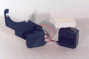
In case you are not familiar with the servo focuser, it consists of a pair of standard model airplane/car servos connected together such that an observer can control focus of a telescope remotely, but without the common overshoot and binary ON/OFF limitations that most commercial focusing motors provide. Best of all, it works without any batteries! In operation, one servo is mounted to your focuser (the “slave”–I use an “O” ring as a drive belt to go from the output shaft of the servo to the focus knob) and the other is held in your hand. When you turn the control arm of the servo in your hand, the nylon gear train in the servo ends up spinning the small DC motor inside quite fast, so fast that it acts as a small generator. Enough voltage/current is produced to travel down the connecting wires to the other servo (on your focuser) and drives the DC motor in that unit. When the servo output arm turns, you get enough oomph to turn your focuser knob. VIOLA!
The “feel” of the thing is quite normal… if you turn the servo arm fast, the focus knob turns fast. If you turn the servo arm slow, the focus knob turns slow. If you reverse direction, the focus knob turns the opposite direction. When you stop, the focus knob STOPS! In other words, it works just like you are turning your focus knob, but you don’t impart any vibration to that 450X view of one of the members of Stephens Quintet! Of course, there are a few limitations:
1) Due to friction and other losses, you don’t get a full 1:1 control; I get about 1.5:1 on mine;
2) If you spin the servo control arm too slow, you won’t generate enough power to turn the “slave” servo;
3) If you are trying to lift a 2 pound Nagler eyepiece straight up, you may have to get a little more creative with your belt drive and external gearing;
4) You have to perform a little minor surgery on the servos (described below).
On the good side, you get:
1) Analog, bi-directional focus control with an intuitive “feel”;
2) Freedom from batteries;
3) It’s cheap! I got my servos from a local hobby shop “junk box” for $2.50 each–any model airplane hobbyist will have a few laying around with missing connectors or bad electronics–this is fine!
Construction
If you already have two servos in front of you, here’s what you need to do to build a servo focuser:
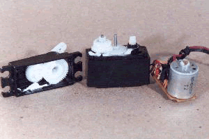
1) Remove the cover that surrounds the electronics, DC motor, and gear train. Be careful to keep track of the layout of the nylon gears – you will need to restore them to their original orientation when you reassemble the servos.
| 2) Remove the small electronics PC board and discard it. You’re only interested in the motor and gear train. You may also need to remove a small potentiometer – more on that in step 4). Just cut the wires. |
|
|
|
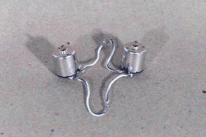
3) Solder two wires that will travel from the two electrical connections on one servo motor directly to the two connections on the other servo motor. You may find a small capacitor to control electrical noise already in place between these connectors. I left the capacitor in place on mine, although I doubt it will make much difference. Be sure to keep in mind any rubber grommet or exit hole in the servo case when you route this pair of wires. Also use enough wire to reach from your focuser to wherever you want the control servo to be–I used about 2 feet of wire. |
4) This step is the only tricky part… Most servos have a small mechanical tab that is used to limit the travel of the output arm of the servo. This tab is usually located on one of the gears in the gear train. Since you want to be able to rotate the servo 360 degrees in either direction, the tab that restricts the rotation must be removed. Different servo brands use different designs, but generally you will be able to find a small tab that runs into a stop at about +- 30 degrees of rotation. Use a file or X-acto knife to trim this tab off. Be VERY careful here, the nylon gears can slip out of your fingers easily and expose your fingers to that razor sharp blade (ask me how I know!). For this reason, I suggest using a file to grind the tab down.
5) Reassemble the servos (you did all of this to both of them, right?). Be sure to get the gear train back into its original configuration. When you give one servo a spin, the other should respond. To make control easier, I attached a wooden handle to the control servo to allow easy handling with gloves on in cold weather.
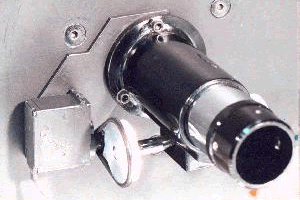
6) Connect the “slave” servo to your focuser. You’re on your own on this one. For my telescope, I attached an aluminum plate below my focuser and the servo was attached to the plate with double-sided foam tape. Make sure the output shaft of the servo is parallel with the focus knob for some kind of O-ring drive belt.
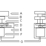
That’s all there is to it. Give it a try! If you have any questions, please send an e-mail to steve2822@earthlink.net and I’ll be happy to help out. Below is a crude cyber-drawing that may be of some help…
Key:
A–Wooden control handle attached to control wheel with small screws
B–Control wheel(s) – this is the standard nylon control arm that comes with a servo. The output belt on the slave servo is held captive on the slave servo by stacking two of these wheels
C–Servo output shaft
D–Gear Train section of the servo (this is where the rotation restriction tab will most likely be found)
E–Empty space where the discarded electronics module came from
F–DC motor with shaft entering the gear train section of the servo
G–Two wires connecting the two servo motors
H–Output shaft that is connected to the focus knob via an O-ring
As for a little background on the cassegrain telescope that my servo focuser was mount on, read on…
The telescope is a 8″ f/16 classical cassegrain. The primary mirror is a parabola (commercial SCTs use a spherical primary and a corrector plate) with an f/4 figure. The secondary is a 2 1/4 inch hyperbolic convex giving a 4x image, giving f/16 at the eyepiece. The optics were made by a company named “Cross” sometime in the late 70’s. I am the third owner of these optics. When I acquired it, the tube assembly included a fiberglass tube and the hardware was all manufactured by Parks. The version shown in the magazines (S&T and Amateur Astronomy) has the fiberglass tube replaced with a truss structure. The truss tubes are carbon fiber arrow shafts (an off the shelf archery product). The rest is just the usual micro-Dob design that should be familiar with most ATMs. If you are interested in a how-to article on constructing a cassegrain (especially the hyperbolic secondary), check out the book How to Make a Telescope by Texereau.
