or When A Bargain Isn’t Necessarily A Bargain
by Steve Bygren, steve2822@earthlink.net
In the spring of 1991, I decided to build my own poncet table for my 10 inch dobsonian. I had recently read a number of articles on poncet tables, and I figured I couldn’t live without one. I decided to build my own because they are relatively straight forward to construct, and the commercial versions cost nearly three times what my telescope cost me to build.
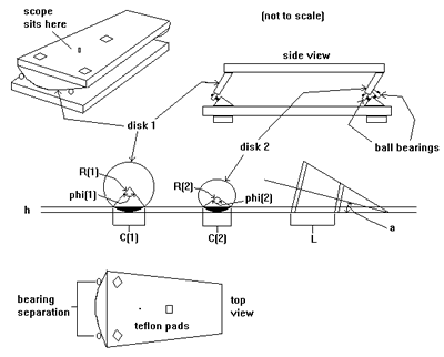
For those of you not familiar with a poncet table, it is a way to get a large alt az telescope to track the sky in right ascension without having an equally large equatorial mount. Where a ‘normal’ equatorial mount will have a telescope connected to a shaft of some kind pointing toward the celestial pole, a poncet table uses a ‘phantom’ axis to perform the same function. From the drawings below, the advantages of a poncet should be apparent:
1) it is compact and lightweight;
2) any dobsonian style telescope can be placed on one; and most importantly to me
3) it can be built at home with only basic power tools.
The disadvantages of a poncet are
1) you can only track for short periods of time before ‘resetting’ the mechanism; and
2) precise photographic tracking is nearly impossible.
Since I was interested in tracking objects at high power with my ‘dob, but not astrophotography, a poncet seemed like a good project to take on.
See the following sketches to make sense of the formulas below.

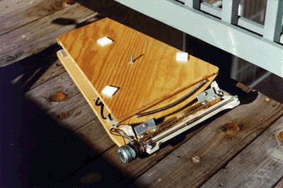
Refer to the following photo of the finished poncet platform.

My first obstacle was to come up with a way to produce smooth round bearings for the cone shaped rotating surface. It occurred to me that most lumber yards carry precut round disks in ‘standard’ diameters. All I needed to do was to come up with the proper geometry to take advantage of these sizes. After lots of sketching, CRC references, and head scratching, I arrived at the following formulas:
let:
R = radius of bearing surfaces (R(1)…large disk, R(2)…small disk)
a = angle to the celestial pole
phi = angle of disk cutouts (phi(1)Large disk, phi(2)Small disk)
L = distance between the large and small disk
C = chord of the disk cutouts (C(1)Large disk, C(2)Small disk)
h = height of the disk cutouts
S = circumference of an arc
initializing:
R(1) = 15 inches (the sizes available to me from a local lumber yard)
R(2) = 6 inches
a = 39 degrees (approx 0.68 radians – we are at approximately 39 deg north latitude)
C(1) = 14 inches (the base of my DOB is approx 14 X 14 inches)
find:
L = (R(1) – R(2)) / sin(a) = 14.3 inches (this value needs to be at least as long as C(1))
phi(1) = 2 * arcsin(C(1) / 2 * R(1)) = 0.97 radians (approx 55 degrees)
h = R(1) – (R(1) * cos(phi(1) / 2)) = 1.73 inches
phi(2) = 2 * arccos((R(2) – h) / R(2)) = 1.56 radians (approx 89 degrees)
C(2) = 2 * R(2) * sin(phi(2) / 2) = 8.43 inches
S(1) = R(1) * phi(1) = 14.55 inches
The goal of these formulas is to determine the depth and separation of the conical sections needed to give me nearly one hour of tracking for my DOB These formulas give me a platform that is about 14 X 14.3 inches, and using C and phi, I can now cut out sections of the precut disks that I purchased at the lumber yard. Since a 30 inch disk will need to rotate 15 degrees per hour, or 3.9 inches, to approximately track the motion of the stars, a bearing separation on the larger disk of about 10.6 inches (14.55 – 3.9) will give the desired hour of tracking. Try your own dimensions and see if it works out for you. For more information on this design, see the “Gleanings for ATMs” article in the September 1988 issue of Sky and Telescope.
With a little ingenuity, I was able to hand cut all the wood pieces and bolt/glue everything together to form the rotating platform of my poncet. The next step was to build a baseboard with the 5 bearing points attached at the correct distances and angles. Because this design uses a ‘virtual’ point of rotation instead of physically rotating about the point of a cone, a 5 point bearing support system was used. Since I expect to do most of my observing at or near 39 degrees of latitude, my bearing supports were attached at this angle. One of the benefits of the 5 point bearing system is that on the small disk, two bearings support from the edge of the disk, and the third supports against the side of the disk. This geometry allowed me to use a piece of 90 degree angle aluminum to attach the bearings. Once the bearings were completed, placing the rotation platform on the base resulted in a very smooth and free moving action. In order to protect the wood disks when the 30-50 pound telescope is riding on top, I glued a strip of 3/4 inch wide aluminum on the wood disk edges, making the motion even smoother. This completed the basic construction of the poncet table. It also ends the genuinely”useful” information in this article.
What follows is the meandering path that lead to a fully functional platform…
The next step in this project was to come up with some kind of drive mechanism. This task led me through the most frustrating part of this project. The dilemma I was faced with was running my poncet on either a low DC voltage, or 110v AC. My initial efforts at driving my table were in an attempt to run on DC. I chose DC because you can easily get from 5 to 12 volts from either a car battery or cells, both of which are easily available whenever I go to Badger Flats. The choice of running DC introduces difficulties in locating a motor and gearing system that will produce the low rotational rates needed to drive the poncet. In a box of electrical odds and ends, I had a couple of DC motors that seemed likely to perform the job adequately and off I went. My first DC motor selection ran at about 8 rpm, and by locating some sophisticated drive train parts (O rings), I had the parts necessary to drive the rotating platform. Once I determined the final output speed of my drive system, I attached the whole mechanism between the base and rotating platform and gave it a try. It became obvious that the mechanism I constructed allowed far too much ‘play’ to drive the platform.
On to plan ‘B’: use a threaded rod/tangent drive common to many tracking platforms. This is the portion of my project that ended up costing the most cash. After hearing how well the machined threaded rod worked on other tables, I headed into the Yellow Pages to find a machinist that could produce the threaded rod sections that I needed to be able to run my table with a 1 rpm motor. Between of the high quality rod that the machinist recommended, and the labor fees he charged to do the work, I spent nearly $50 just for two pieces of 3/8 inch 24 tpi rod. (ouch!) Suddenly, I realized why the commercial operations selling poncet tables were charging so much for them. With that experience behind me, I scavenged through my other odds and ends boxes to produce the bearings, brackets, and springs needed to complete the tangent drive. Now I had to restart my search for a suitable DC motor to run this thing. It was about this time that it occurred to me to use a stepper motor with either a dedicated stepper controller or use my PC to control it. Since I had an article describing the construction of a stepper motor interface that used a PC printer port and a BASIC program to control a motor, I figured that it was only a matter of time before I would have a low voltage DC motor running at whatever speed I setup in the BASIC program. Well, to make a long story short, the PC, program, interface card, and stepper motor all worked as predicted, BUT, the torque was too low to reliably drive my tangent arm setup, not to mention that the batteries in my computer were being drained unusually fast by all the I/O to the printer port.
On to plan ‘C’: build or buy a power inverter and run a 110 VAC synchronous motor to drive the poncet. A 110 VAC 1rpm motor was easily found with a trip to a local surplus/scrap dealer (OEM Parts in Colorado Springs). Incidentally, nearly all of my projects are made up of parts from this unusual store. Back to my story…
I discovered a VERY old power inverter that used a noisy, vibrating mechanical relay and capacitor to generate 110 VAC from a car battery. It could only produce 10 watts, but after gingerly connecting it to my poncet and turning it on, to my surprise, IT WORKED! I put my DOB on the table, and it still worked! I could finally see light at the end of the tunnel. I even took the whole assembly out to out local observing site, Badger Flats, to give it a real test run. For nearly 2 hours, it seemed that I finally had a stable, reasonably accurate drive to allow me to crank up the power without having to constantly tug the scope around to keep an object within my field of view. I was eager to tell someone of my success, and strolled over to some of the other observers present to brag about my belated success. When I returned with some willing guinea pigs to test it out, I noticed the lack of noise near my setup. Silence…that OLD power inverter I was using fried itself and was now producing an odor that was only slightly less offensive than a skunk! Back to the drawing board.
Lets see, this must be plan ‘D’… I had a working system that only needed a reliable source of 110 VAC power. The decision to be made now was whether to buy a commercial inverter to generate the 110 VAC from the 12 VDC available from my car battery, or to build one based on yet another article I had been saving from an appendix of Michael Covington’s astrophotography book. Thinking that I could build one much cheaper than the $75 that a new one would cost, off to Radio Shack I went. After spending about half what a new inverter would cost, I had all the fixin’s to produce a variable frequency inverter that ought to do the job. I spent the next week soldering and drilling and taping everything and I finally had what I hope will be my last boondoggle on this project.
As of this writing, I have a functional poncet table that does a pretty good job of pulling my DOB around the sky, and although I spent a bit more that I expected to, and worked a lot more then I planned to, I have the poncet that I yearned for nearly 18 months ago. Would I do it over again if I knew then what I knew now? SURE I would. The drive system and motor were a bit of a hassle, but the use of precut wood disks made it all much easier than if I had tried to cut them by hand. Considering that a commercially build poncet platform can cost between $800 and $2400, my project was a bargain even with the dead ends that I followed.
